

Technical Specifications of Excavator Track Roller
Apr 24, 2024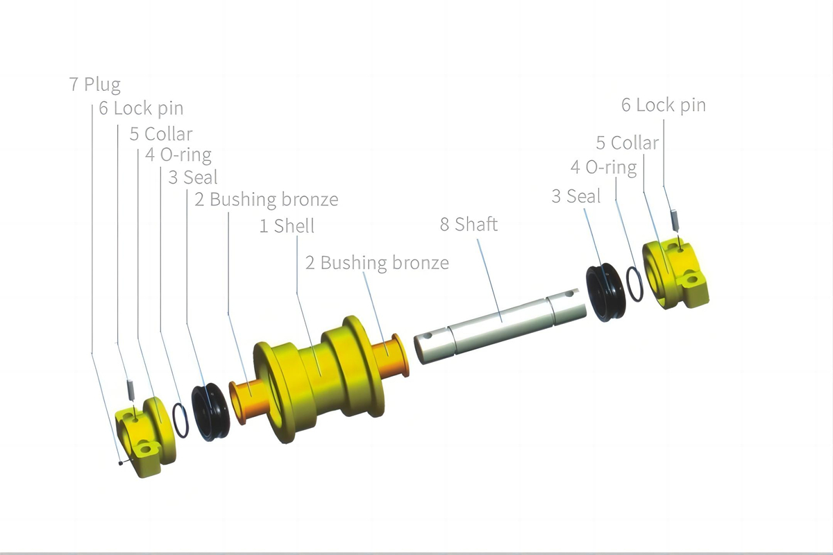
The material of the main shaft is high-quality 50Mn carbon structural steel, with a C content of 0.48% to 0.56%, Si content of 0.17% to 0.37%, Mn content of 0.7% to 1.0%, S content less than 0.035%, P content less than 0.035%, Cr content less than 0.25%, Ni content less than 0.30%, and Cu content less than 0.25%. Among them, Mn is an important element in alloy steel, which can improve the forgeability and plasticity of the steel, ensuring that the material has sufficient toughness and wear resistance. After heat treatment, 50Mn steel has high strength and hardness, excellent hardenability, a deep hardened layer, fine pearlite structure, and good mechanical properties.
The design standard for the main shaft requires a quenching depth (T) of 2 to 7mm, and a quenching hardness of 50 to 62 HRC.
The wheel body of the supporting wheel endures frequent impact loads on the track surface, which can lead to deformation and the extension of the track surface into a conical shape. To improve the load conditions, the length of the track surface on the wheel body has been increased, and the transition between the track surface and the wheel waist is designed with a slope to enhance the support capacity of the track surface.
To improve the wear resistance of the wheel body, the material used is 40Mn2 alloy structural steel, with a C content of 0.37% to 0.44%, Si content of 0.17% to 0.37%, Mn content of 1.4% to 1.8%, P content less than 0.030%, and S content less than 0.030%.
The wheel body is formed by forging and then subjected to quenching and tempering treatment to achieve a hardness of 26 to 32 HRC, ensuring the wheel body has high strength, plasticity, toughness, and comprehensive mechanical properties internally. The surface of the wheel body undergoes quenching treatment to improve the hardness and wear resistance of the track surface of the supporting wheel. The quenching hardness is 50 to 58 HRC, and the quenching depth is 6 to 12mm, resulting in the track surface hardness being close to the hardness of the chain rail joints (48 to 58 HRC).
The dimensions and surface roughness of the O-ring seal groove should meet the design requirements, mating surfaces should be chamfered, and burrs and sharp edges should be cleaned.
High-quality nitrile rubber should be used for the floating seal ring and O-ring seal, with inner diameter dimensions, wire diameter dimensions, elasticity, hardness (Shore), and surface finish meeting the standards. Before assembly, each of the above items should be inspected individually to ensure they meet the requirements before being assembled.
If the floating seal ring does not fit snugly into the floating seal ring groove or does not align properly with the floating seal ring, uneven pressure on the floating seal ring can occur. Uneven pressure can lead to increased localized wear on the floating seal ring during rotation, resulting in oil leakage. If the O-ring seal is damaged at the edge when assembling the inner and outer covers, or if it is twisted during installation into the groove, it can reduce the sealing performance or lifespan of the O-ring seal. Sometimes, if the airtightness check pressure does not reach a certain value, leaks may not be detected, and even after oiling, leaks may not occur. However, after the excavator operates for a certain period, the friction and temperature rise of the various components of the supporting wheel, and the internal pressure reaches a certain value, leaks may occur. Continued use after a leak occurs can lead to severe oil leakage from the floating oil seal.
The clearance between the main shaft of the supporting wheel and the shaft sleeve on the wheel body should be 0.2 to 0.4mm, with no obstruction during rotation and good sealing performance to prevent oil leakage.
For lubrication, gear oil should be added to the supporting wheel using an oiler, and the viscosity of the lubricating oil can be increased as needed. Before adding gear oil, the old gear oil should be drained, and then new gear oil should be added through the oil plug hole until the oil flows out. When adding lubricating oil, unscrew the end cap screw of the shaft, place the nozzle of the oiler against the shoulder inside the oil passage, and inject the oil into the oil passage. When installing the oil plug, a torque wrench should be used to tighten the oil plug to a torque of 157 to 255 N•m.
Address : Building 17, Block 9, Section D, 27th Road, Chenghui International Hardware and Electrical City, Xiamei Town, Nan'an City, Quanzhou, Fujian Province
Wechat :

Please read on, stay posted, subscribe, and we welcome you to tell us what you think.
Copyright © 2024 Quanzhou Futeng Machinery Engineering Co.,Ltd All Rights Reserved.
Sitemap
|
Blog
|
Xml
|
Privacy Policy
 Network Supported
 English
 English
 Русский
 Español


